Here are all of the files of the SolidWorks parts, drawings, and assemblies that have been made/used over the course of this project. The servo motor that was used is an assembly, so all of its parts are located in a separate folder.
https://drive.google.com/folderview?id=0B2YG3caqyrOeVF9HeUhYUlBtN3M&usp=sharing
Thursday, December 12, 2013
Wednesday, December 11, 2013
Final Design Update
Team Rubber Band Gunner had a final meeting on Wednesday, December 11, from 2:30 pm to 5 pm in Perry 321. In this meeting, the team completed the assembly, tested the mechanism, and made appropriate adjustments. All members of the team were present for this meeting, and all members participated equally in each aspect of the meeting.

Overall, the mechanism performs what it is intended to do, which is launch rubber bands and indicate when it needs to be reloaded. However, it does not perform to its fullest extent because it is unable to hold multiple rubber bands.
After completing this project, there are a few changes that would be made if the team were to do it again. First, some simple changes would be made to the gear that was 3D printed. The center hole would be cut to fit directly on the servo motor, so that a servo horn or any adhesive would not be needed. Also, the edges of the gear would be rounded to make sure that rubber bands would not get caught on pointed edges while launching (a problem that doesn't occur often, but occasionally). Here is what the re-designed gear would look like:

Also, if possible, a stronger, more powerful servo motor would need to be purchased, so that more rubber bands could be placed on the gear without the servo motor rotating on its own.
Finishing the assembly was an easy process. The team purchased Epoxy adhesive to attach the servo horn to the gear. The adhesive was spread over the gear, the servo horn was placed on the gear, and pressure was put on the servo horn for about 30 minuets. To ensure that the servo horn and gear would have as little independent movement as possible, electrical tape was placed over the servo horn on the gear after the adhesive dried. Here is a close-up view of the attachment between the two parts:

The team also made a slight change in the mechanism's assembly from its initial assembly that was created in SolidWorks (shown in Week 3 Design Update). Instead of placing the Arduino Uno board on the side of the base, the bread board was placed on the side of the base. This adjustment allowed the Arduino board to connect to a computer without the USB cable possibly getting in the mechanism's way. The bread board is designed with adhesive on the bottom, so it was simply placed on the mechanism's base. Some electrical tape was also put on the launching arm to make it a bit sturdier. Here are some pictures of the completed mechanism:
 |
| Side 1 |
 |
| Side 2 |
Once testing began, the team noticed a clear problem. The mechanism could support one rubber band, but once two, three, and four rubber bands were placed onto the mechanism, the servo motor began to rotate on its own due the force from the rubber bands. Also, the force of the rubber bands caused the gear's position on the servo horn to shift slightly. After initial testing, it was clear that this specific mechanism should launch one rubber band at a time.
In order to allow the mechanism to launch one rubber band at a time, the Arduino code needed to be adjusted. The code was changed so that the servo motor alternated between two different positions: its initial "reload" position, and its position after launch. The difference between these two positions was made very large, so that servo motor can make a large rotation, and the rubber band is guaranteed to launch every time. If the servo motor does not rotate enough, then the rubber band will most likely remain on the gear. Here is the updated code:
And here is a video of the mechanism in action:
Overall, the mechanism performs what it is intended to do, which is launch rubber bands and indicate when it needs to be reloaded. However, it does not perform to its fullest extent because it is unable to hold multiple rubber bands.
After completing this project, there are a few changes that would be made if the team were to do it again. First, some simple changes would be made to the gear that was 3D printed. The center hole would be cut to fit directly on the servo motor, so that a servo horn or any adhesive would not be needed. Also, the edges of the gear would be rounded to make sure that rubber bands would not get caught on pointed edges while launching (a problem that doesn't occur often, but occasionally). Here is what the re-designed gear would look like:

 |
| A close-up of the center hole, cut to fit a servo motor |
Sunday, December 8, 2013
Week 5 Progress Summary
During the week of December 2-6, team Rubber Band Gunner met on Wednesday, December 4, and Thursday, December 5. All team members were present for these meetings. During these meetings, the team assembled most of the mechanism, began the written project summary, and created the teams final goals before presentation. No changes were made in the mechanism's Arduino code.
On Wednesday, December 4, the team met from 3-5pm in Donahue Hall. Before this meeting, the team traveled to Lowe's to buy some rubber bands and find adhesive appropriate for attaching the fabricated gear with the servo horn. We ended up purchasing Gorilla Super Glue, which is suitable for most plastics. However, because of the small rivets on the surface of the gear, the glue was unable to attach it to the servo horn. The team decided to continue with assembly of the rest of the mechanism by screwing the both the launching arm and the servo motor into the base.
On Thursday, December 5, the team met from 2:45-4:30 in Lydon Library. By this point, a proper adhesive for the gear and servo horn had not been found. Therefore, the team decided to begin writing the project summary and plan for future meetings. The team managed to complete a rough draft of the written project summary during this meeting.
For next week, before project presentations, the team plans to find a proper adhesive for the gear and servo horn. If a proper glue cannot be found, then the team will have to use Gaffer's tape or duct tape in order to attach the two. After the attachment, the team will be able to perform testing on the mechanism. The only likely adjustment to be made will be a small adjustment to the Arduino code. The gear will need to be able rotate a proper amount to release 1 rubber band for every press of the button. The team will find out that appropriate rotation during testing.
About 1 hour of individual work was performed by each team member during the week. All members spent the hour on finishing part drawings in SolidWorks. Jordan Parris finished the gear, Andrew Muise finished the base, and Justin Belli finished the launching arm, all of which are displayed in the previous post.
Thursday, December 5, 2013
Week 5 Design Update
All of the parts of team Rubber Band Gunner's mechanism that needed to be created have finally been created and are ready for assembly. The gear was fabricated using a 3D printer, and the base and launching arm were constructed from wood by team member Andrew Muise. Also, a servo motor of appropriate size for the mechanism was purchased from RadioShack. This is because the servo motor belonging to the Sparkfun Inventor's Kit was too small compared to the servo motor imported into SolidWorks from grabcad.com earlier in the design process. The rest of the Inventor's Kit parts shown in earlier testing are still being used in the mechanism. Here is a picture of all of the mechanism's parts:

During this week's meetings, the team began assembly of the mechanism. So far, both the launching arm and servo motor have been attached to the base using screws. The servo horn needed to be firmly attached to the gear in order for testing of the entire mechanism to begin. However, the adhesive purchased to attach the two was not strong enough for testing. The team's current objective is to find adhesive or tape that is not only strong enough to attach the gear to the servo horn, but also strong enough to allow up to four rubber bands to hold onto the gear while the mechanism is operating. Once a solution to this problem is found, initial testing can begin.
For now, here are the drawings of all parts of the mechanism that were created from scratch on SolidWorks.
During production of the base and launching arm, a decision was made to cut the hole for the servo motor entirely through the side of the base. This design is slightly different than the initial base design, shown in the week 3 design update. The design was adjusted in SolidWorks, and the update is displayed in the drawing above.

During this week's meetings, the team began assembly of the mechanism. So far, both the launching arm and servo motor have been attached to the base using screws. The servo horn needed to be firmly attached to the gear in order for testing of the entire mechanism to begin. However, the adhesive purchased to attach the two was not strong enough for testing. The team's current objective is to find adhesive or tape that is not only strong enough to attach the gear to the servo horn, but also strong enough to allow up to four rubber bands to hold onto the gear while the mechanism is operating. Once a solution to this problem is found, initial testing can begin.
For now, here are the drawings of all parts of the mechanism that were created from scratch on SolidWorks.
 |
| Gear |
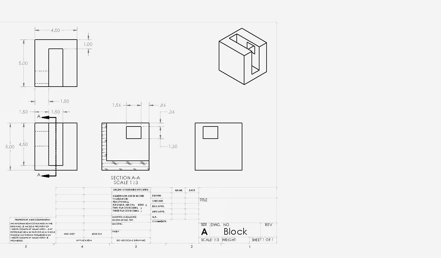 |
| Base |
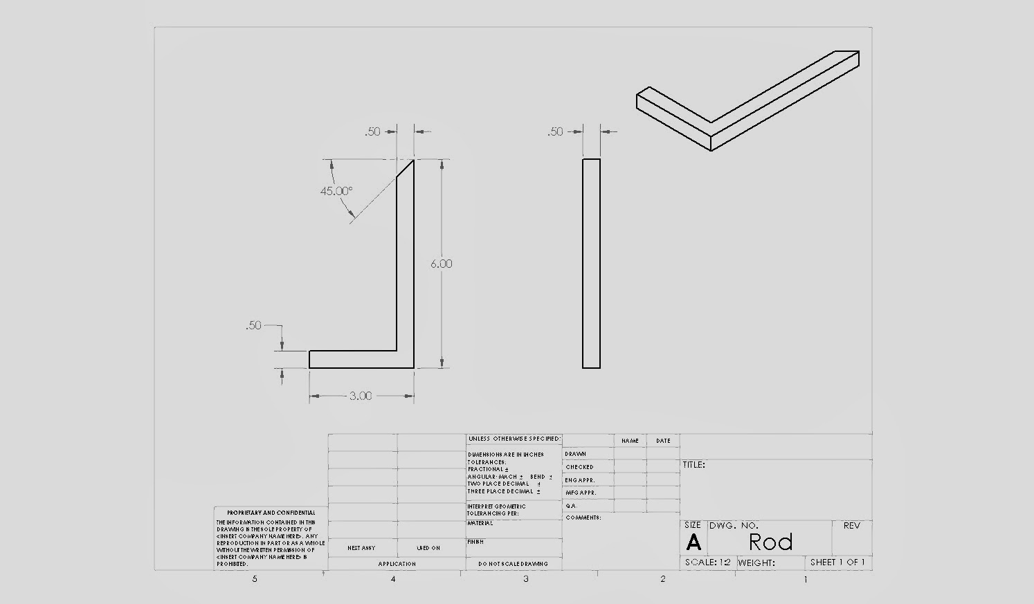 |
| Launching Arm |
Sunday, December 1, 2013
Week 4 Progress Summary
During the week of November 25-29, team Rubber Band Gunner met once, on Monday, November 25 from 4-6 pm in Perry 311. All team members were present for this meeting, and all goals intended for this meeting were accomplished.
During this meeting, the team updated the mechanism's Arduino code in order to adjust the LCD screen display. The team also adjusted one part of the mechanism so that it could be fabricated. Both accomplishments are described in detail in the previous post.
Since the accomplishments for this week were rather simple, the team decided to continue the week's progress by splitting up different individual tasks to help accomplish future goals. Team member Jordan Parris took on the role of updating the blog, while team member Justin Belli took the role of starting SolidWorks drawings for each part of the mechanism, and team member Andrew Muise began the creation of certain parts of the mechanism using wood. Each member spent roughly 2-3 hours on an individual task.
For next week, the team plans to begin the assembly and testing of the actual mechanism, as well as post the finished drawings of each part of the mechanism. Individual work by each team member has so far helped the team reach these goals.
Tuesday, November 26, 2013
Week 4 Design Update
In order for our mechanism's gear to be fabricated, it needs to have a specific thickness of either 0.125" of 0.25". In SolidWorks the gear's thickness was adjusted from 0.5" to 0.25". To ensure that an appropriate amount of material was used, the gear, having a 4 inch diameter, was shelled to make the majority of the inside hollow. This gave the gear an appropriate volume of material, only 2.07 in.^3. Here is a picture of the final product, ready for fabrication.
The Arduino code was also updated so that the LCD screen displays "RELOAD" when the servo motor is in its initial position. In this position, rubber bands can be loaded onto the mechanism, so that they can be fired as the servo motor changes positions. The code was also adjusted so that after it is uploaded, the servo motor moves directly to its initial position. Here is the code:
And here is a video of the code in action:
 |
| Gear to be fabricated, with adjusted thickness and material volume. |
The Arduino code was also updated so that the LCD screen displays "RELOAD" when the servo motor is in its initial position. In this position, rubber bands can be loaded onto the mechanism, so that they can be fired as the servo motor changes positions. The code was also adjusted so that after it is uploaded, the servo motor moves directly to its initial position. Here is the code:
And here is a video of the code in action:
Sunday, November 24, 2013
Week 3 Progress Summary
During the week of November 18-22 team Rubber Band Gunner met on Wednesday, November 20, and Thursday, November 21. All team members were present at both meetings.
Before team meetings each member worked individually to brainstorm ideas for the overall mechanism. With the gear already designed, a base to hold the gear and servo motor, and an arm to launch the rubber bands needed to also be designed. Each member spent roughly one hour on individual work.
Wednesday meeting: Team Rubber Band Gunner met from 2pm to 4:30pm in Perry 321. During this meeting, the team finalized the design of our mechanism's gear, which is planned to be fabricated. The team also brought together individual designs and created all other parts of the mechanism on SolidWorks (listed in previous post). Some parts were used from grabcad.com, while others were created from scratch in SolidWorks (specified in previous post). The decision was made to attach the gear to a servo horn on the servo motor using adhesive, rather than cut a hole in the gear to fit on the servo motor. Also, the team decided to angle the top of the launching arm in order to avoid the rubber bands hitting the mechanism's arm as they launch. Finally, the team created an assembly in SolidWorks using all of the parts (displayed in previous post).
Thursday meeting: Team Rubber Band Gunner met from 4pm to 5:30pm in Perry 321. During this meeting, the team created a motion analysis of the assembly in SolidWorks that was created in the previous meeting. In the motion analysis, the servo motor rotates, causing the servo horn and gear to also rotate which would launch rubber bands over the launching arm, or prepare the mechanism to reload. The team also discussed intentions for next week.
For next week, the team plans to fabricate the gear that was created. Also, the team plans to update the mechanism's Arduino code, since the code for the mechanism has not been updated since week 2. The code is expected to allow the LCD screen to display "RELOAD" when the servo motor resets to its initial position.
Subscribe to:
Comments (Atom)